
Product Manual
Electric Utility Vehicle • Product Manual
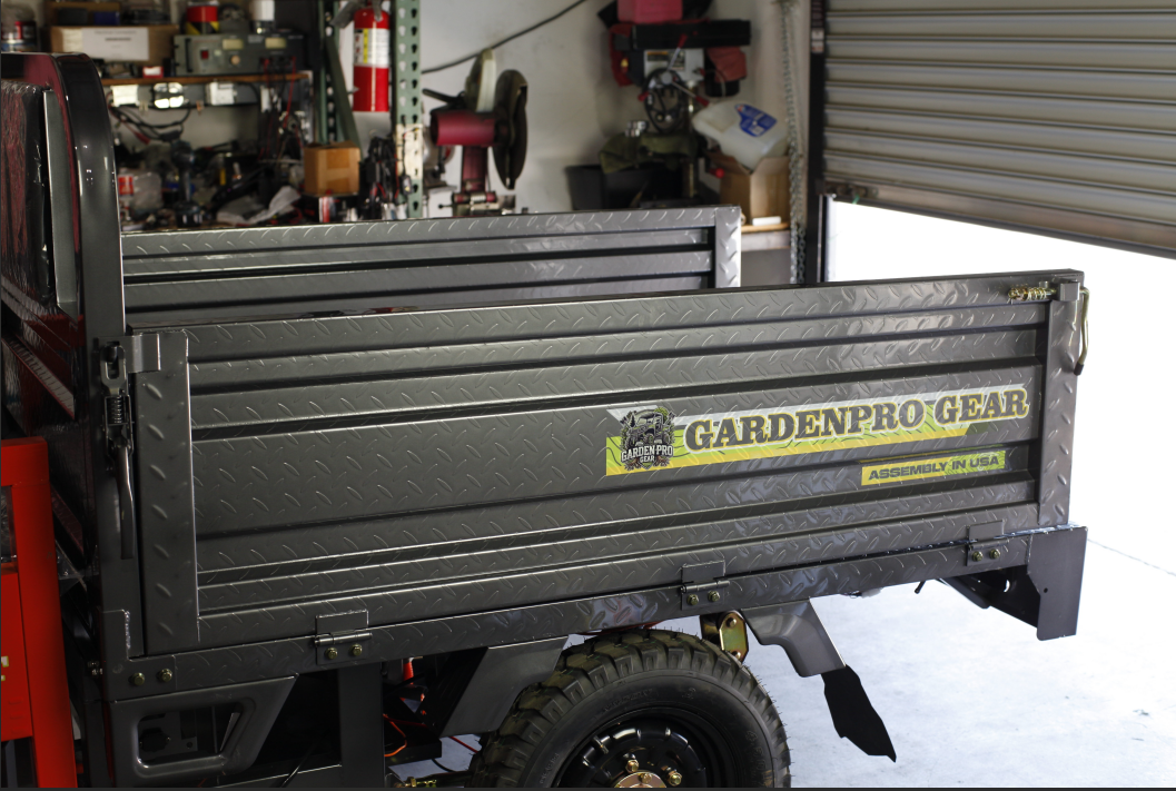
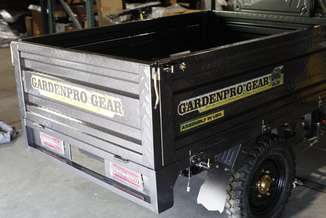
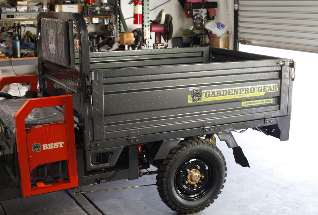
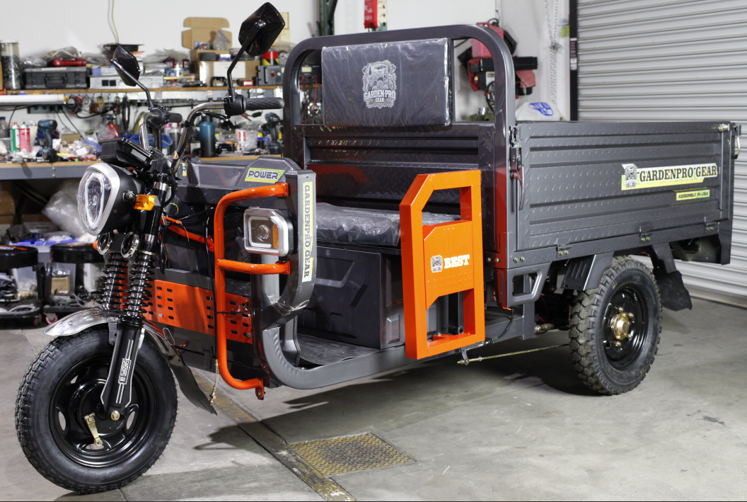
Discover every highlight of our latest electric utility vehicles. Browse stunning images, detailed specifications, and unified core features engineered for performance and durability.

Standard Features (All Models)
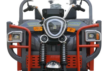
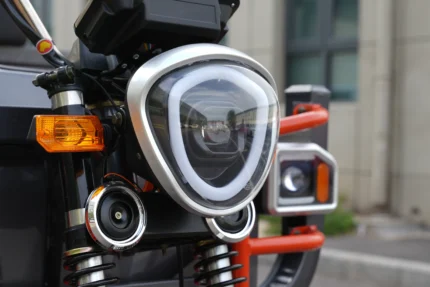
- LED projector headlamp with Aurora-style beams
- High-intensity square LED perimeter lights & flowing rear tail lamp
- Crystal-clear LED dashboard
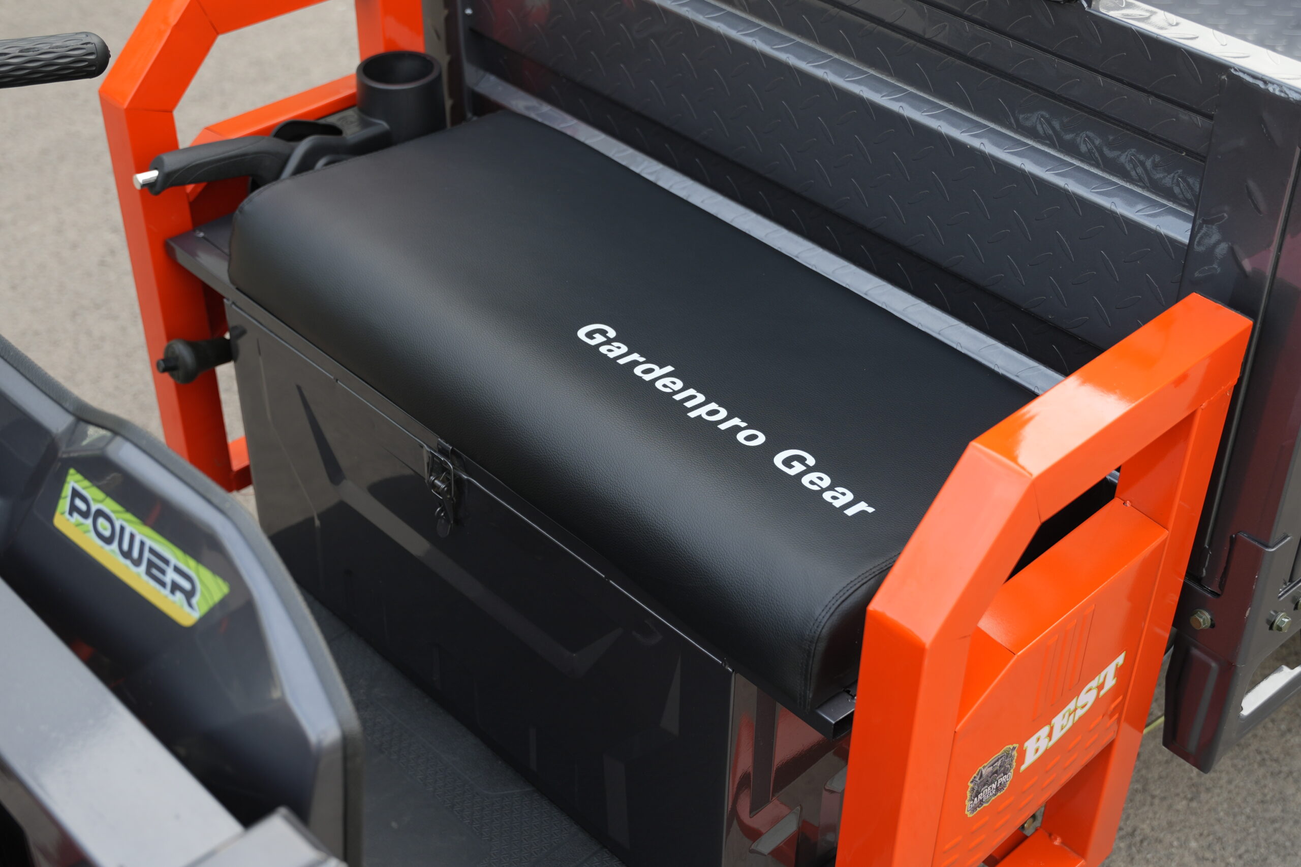
- Wear-resistant foam seat cushion & backrest
- National-standard 6 mm² copper wiring harness
- Military-grade green fasteners throughout
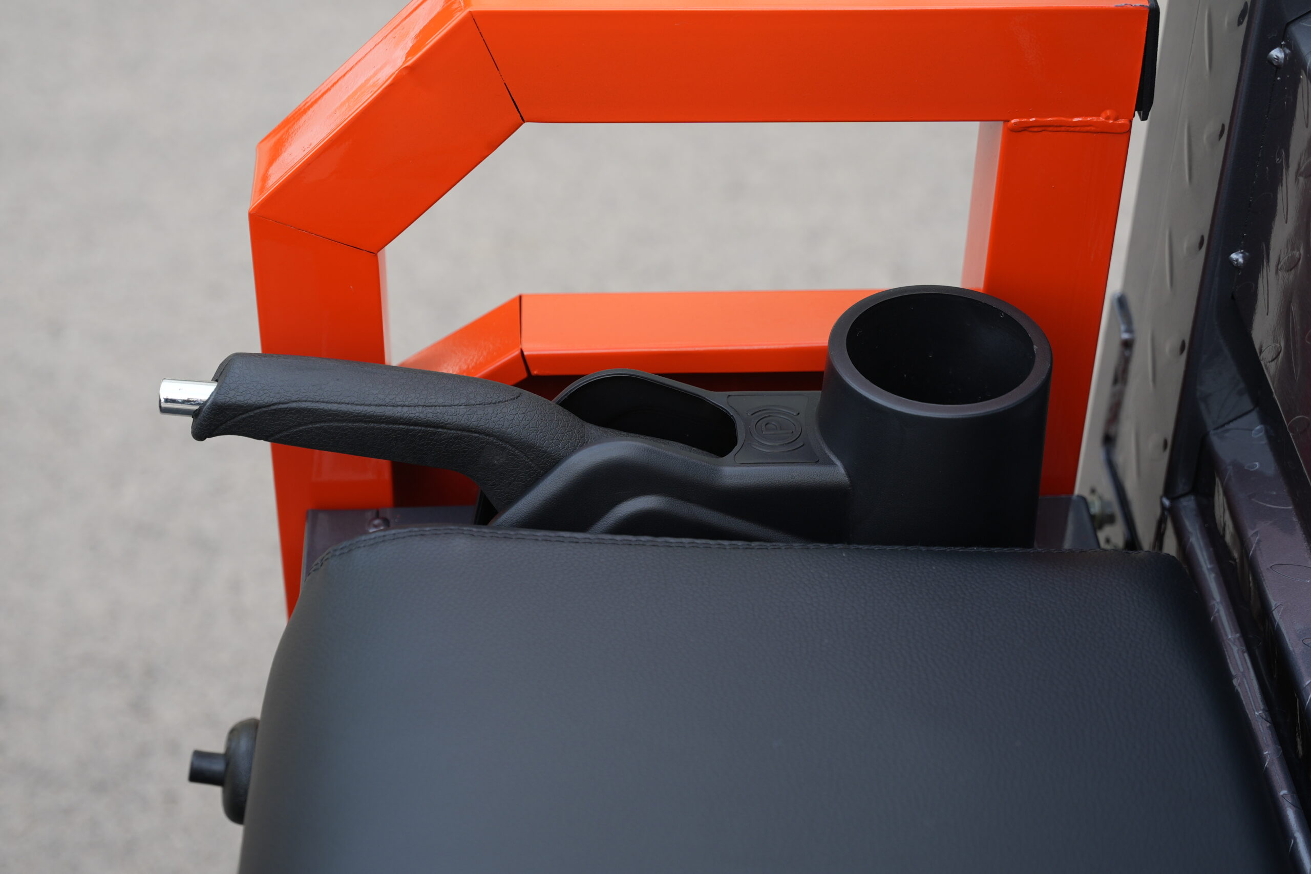
- Automotive-style handbrake system
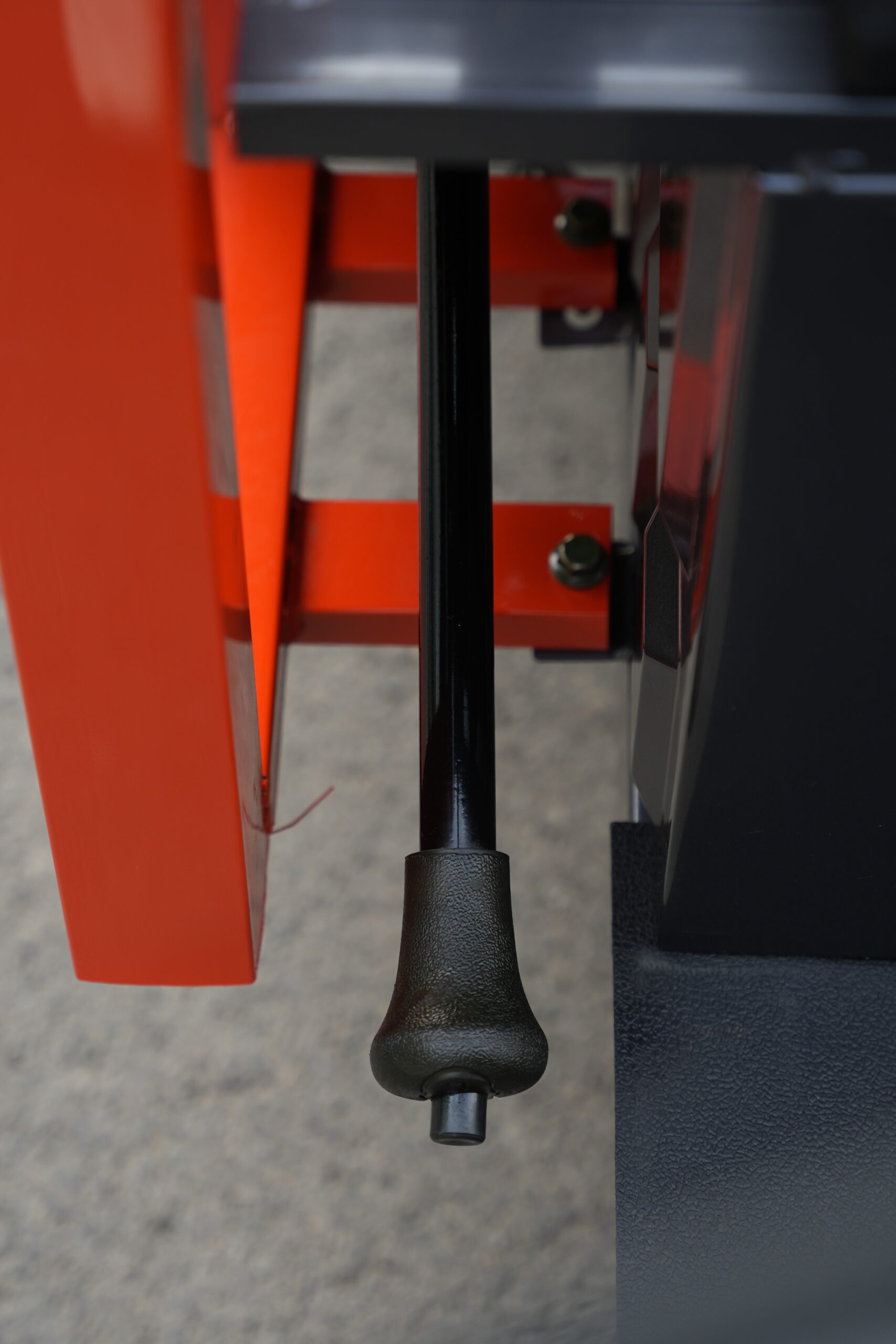
- Reinforced one-piece gear-shift lever
- National-standard pressure-relief dampers
- Body panels & cargo box made from national-standard steel
Model 1.5 / 1.6 Specifications
| Dimensions (L × W) | 3.0 m × 1.1 m / 3.1 m × 1.1 m |
|---|---|
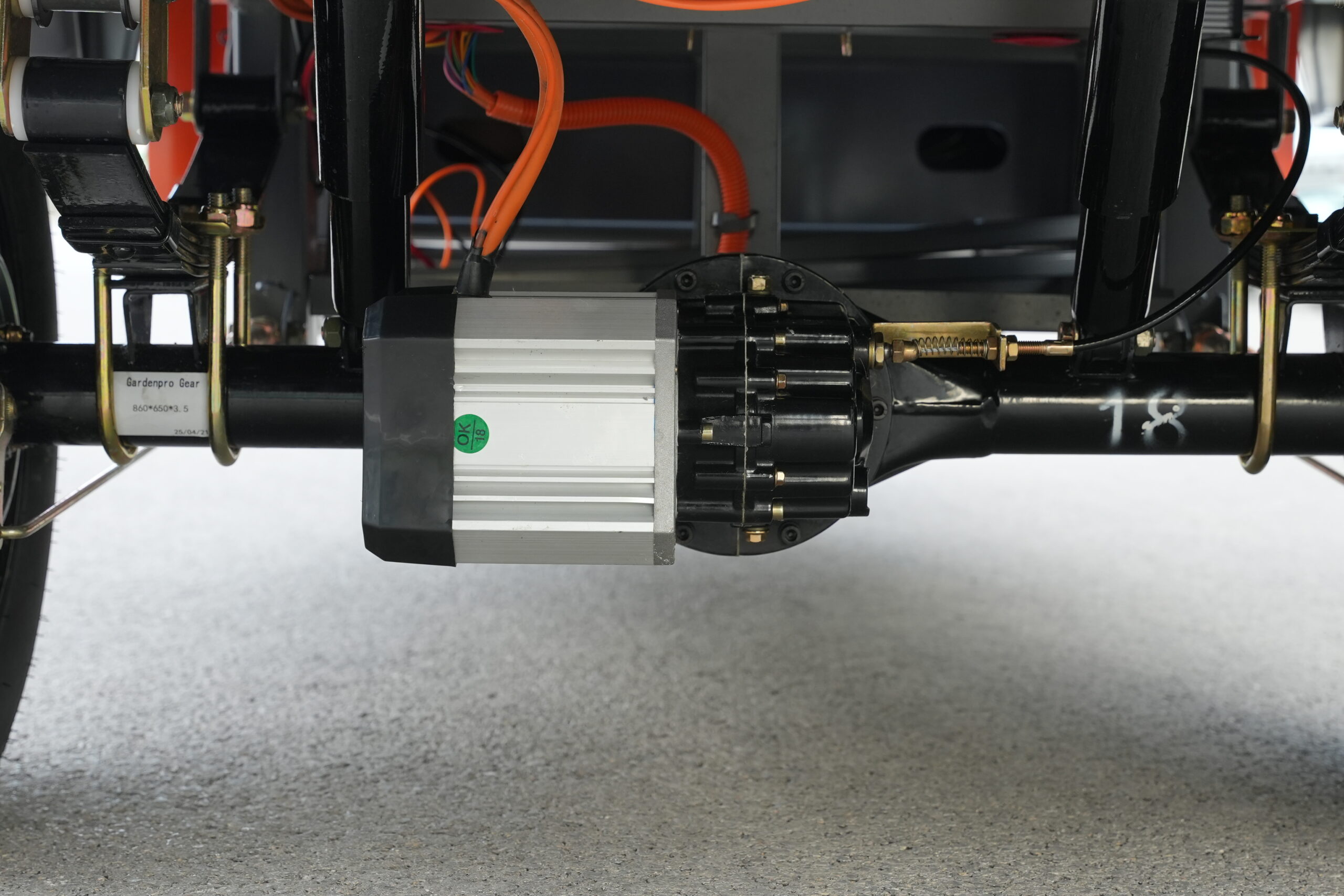
| Motor | 1,200 W Permanent-Magnet Synchronous Motor |
| Rear Axle | 160 mm Integrated Floating Axle |
| Controller | 24-tube Single-row Controller |
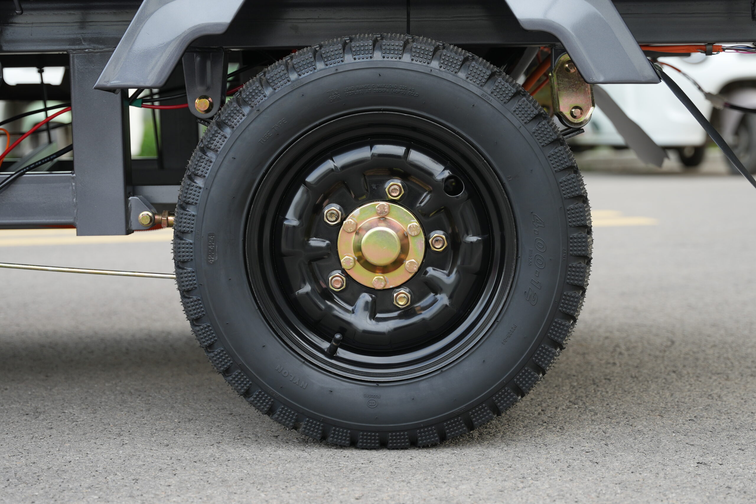
| Tires | Front 375 / Rear 400 Dome Tires |
| Leaf Springs | 8 kg Steel Leaf Springs |
| Shock Absorbers | Ø37 mm One-piece Forged Spring Shocks |
| Handle | Split Gear-shift Twist Grip |
Model 1.8 Specifications
| Dimensions (L × W) | 3.3 m × 1.3 m |
|---|---|
| Motor | 1,800 W Magnetic Cube Motor |
| Rear Axle | 220 mm Integrated Gear-shift Full-floating Axle |
| Controller | 30-tube Controller |
| Tires | Front 400 / Rear 450 Steel-wire Flat-top Tires |
| Leaf Springs | Dual 8 kg Steel Leaf Springs |
| Shock Absorbers | Ø43 mm One-piece Forged Spring Shocks |
| Handle | Integrated Stainless Gear-shift Twist Grip |
Installation Guide
Follow these detailed steps to install your electric utility vehicle. Each step includes clear illustrated instructions to ensure proper installation.
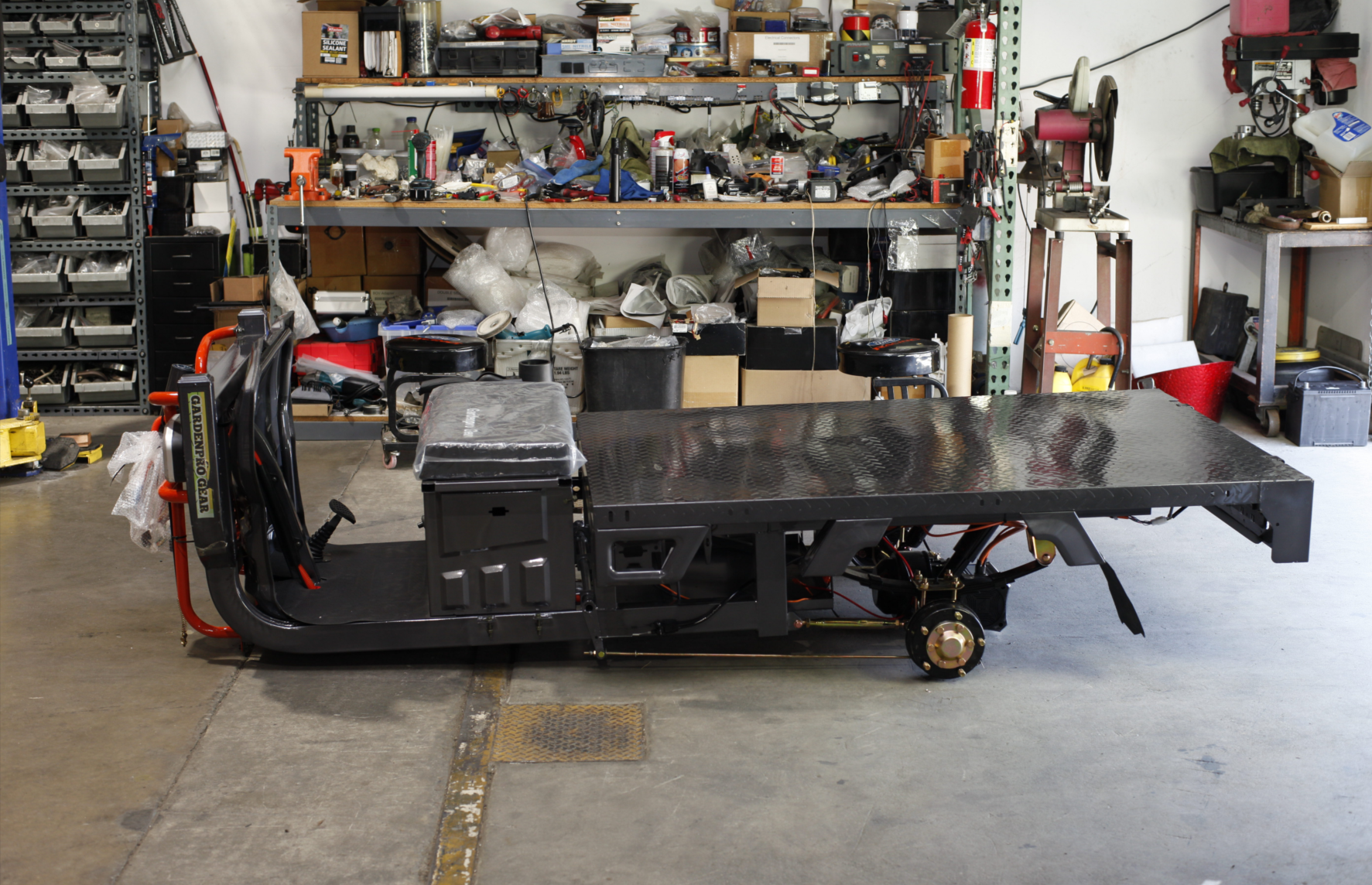
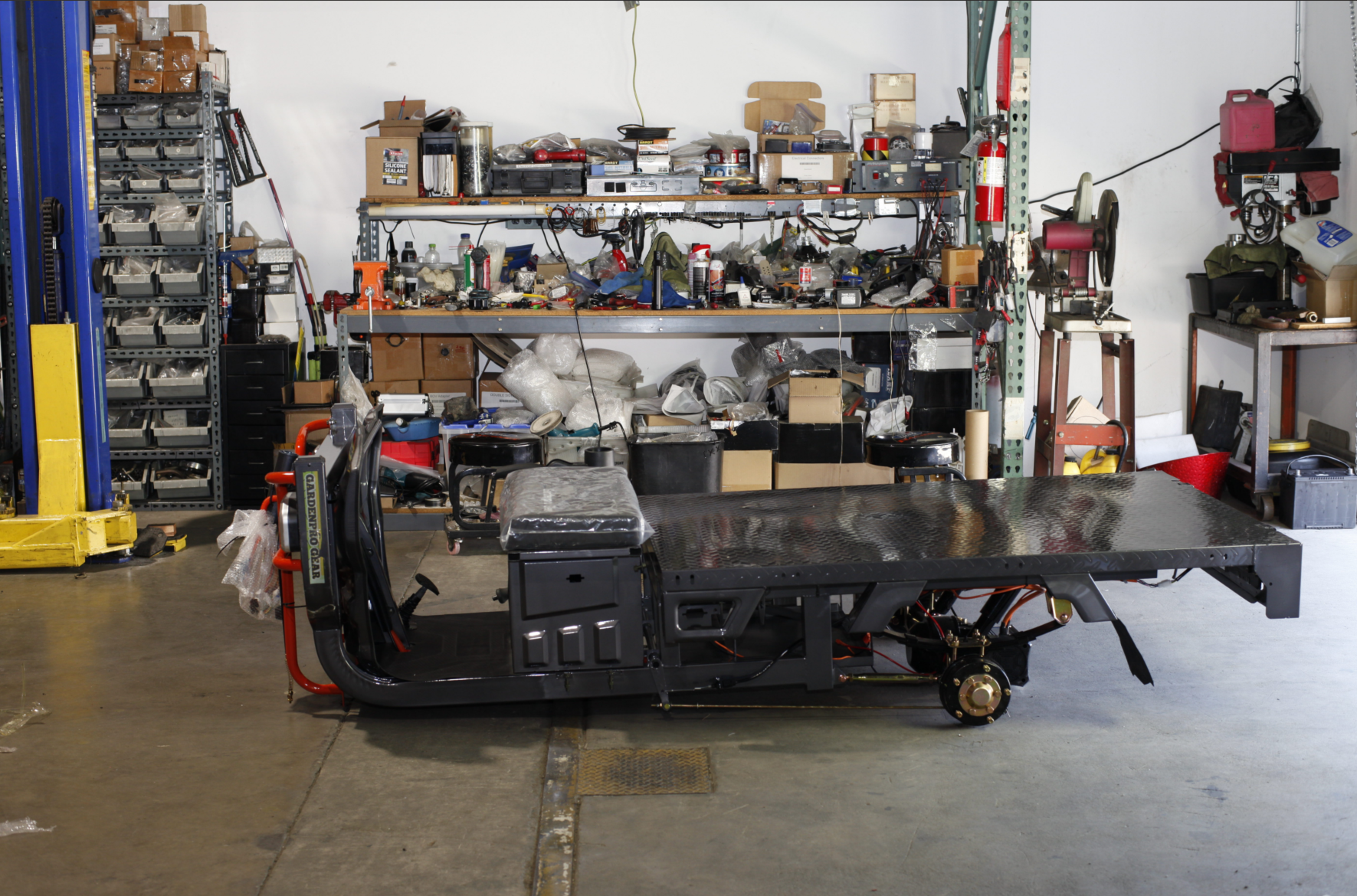
1Position the Frame Parallel
First, place the frame steadily on a flat ground surface, ensuring the frame remains parallel and stable.
2Install Vehicle Rear Wheels
Install the rear wheel assembly to the rear section of the frame, ensuring the tires are aligned with the frame and securely fastened.
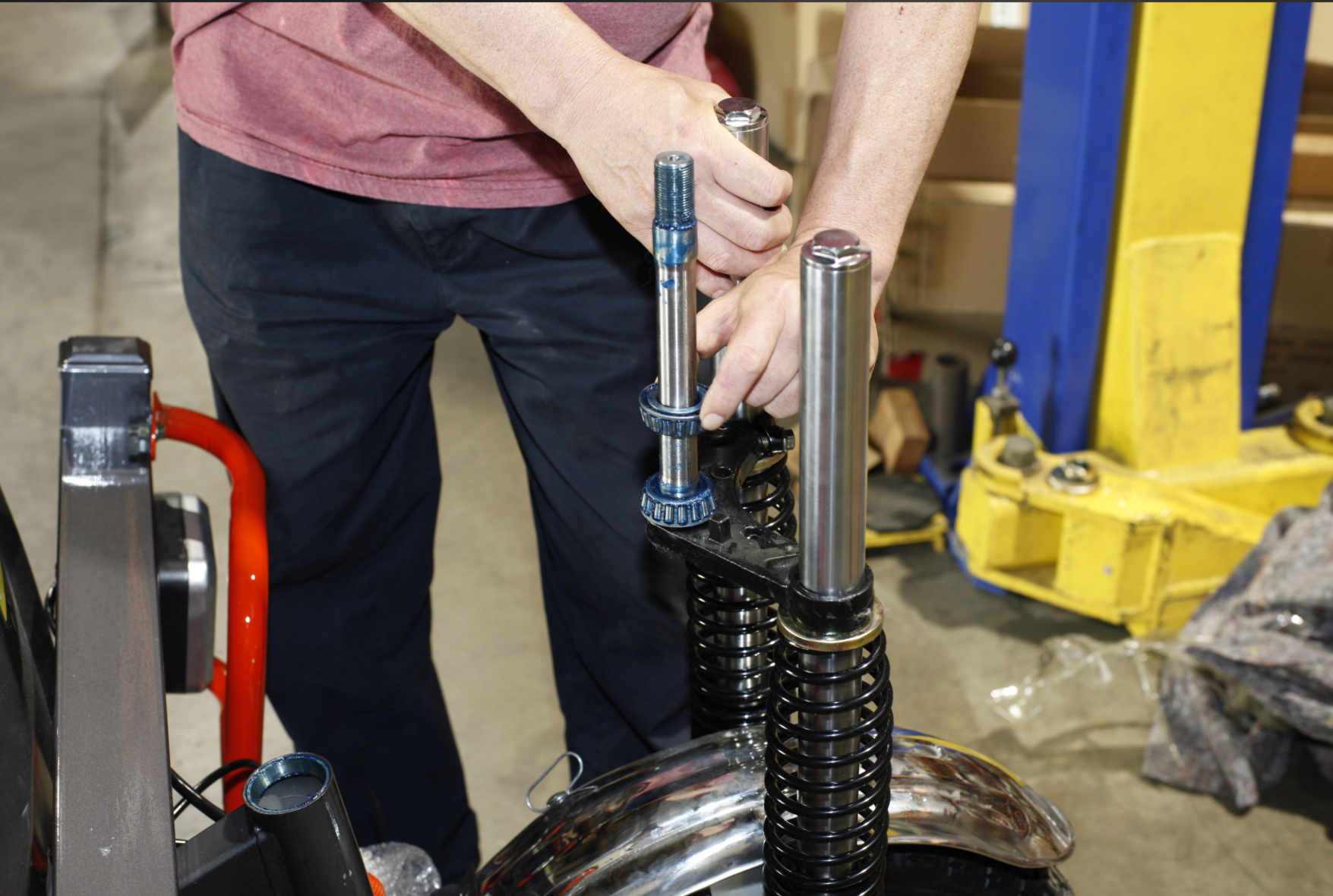
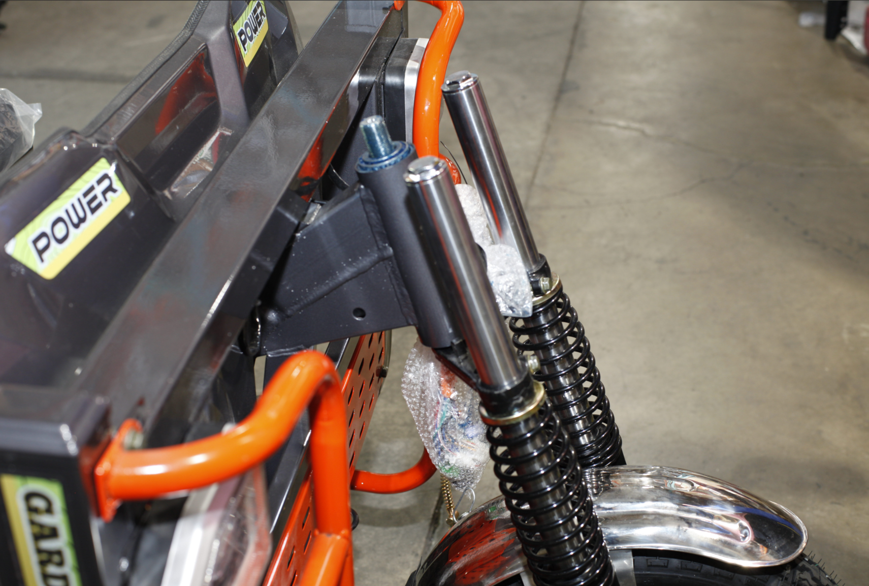
3Install Connector and Bearing System
This is a critical step that requires careful operation following the sub-steps below:
3.1 Check Connector Bearing
The connector bearing is divided into upper and lower sides. Ensure all components are complete.

3.2 Remove Upper Bearing
Carefully remove the upper bearing component to avoid damage.
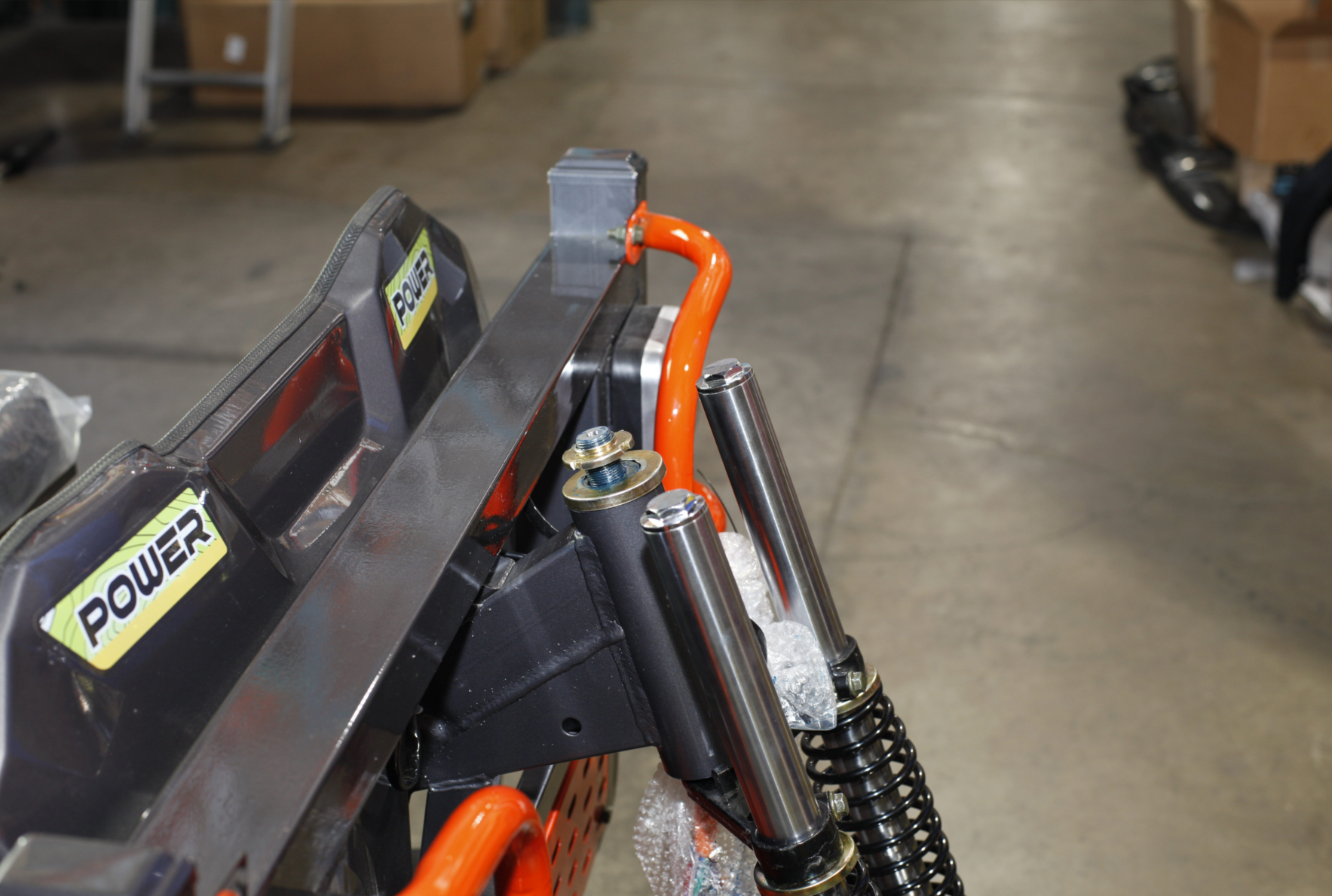
3.3 Align with Diagonal Beam Upper Opening
Align the connector with the upper opening position of the diagonal beam.
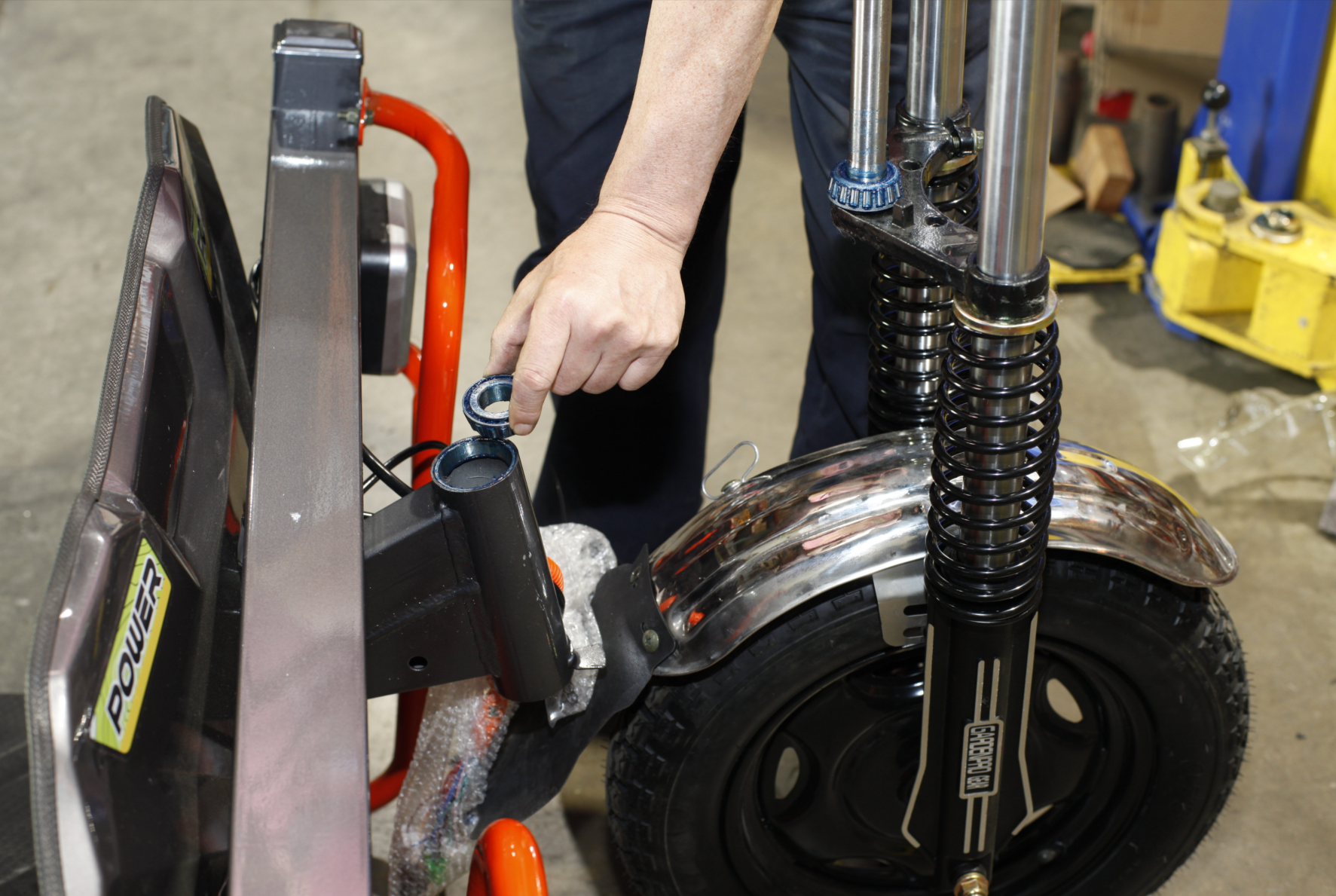
3.4 Lift Front Frame
Lift the front frame and align the connector with the lower opening of the diagonal beam for insertion.
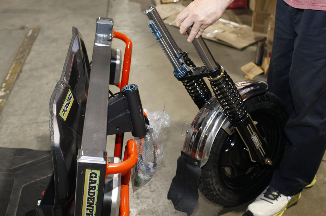
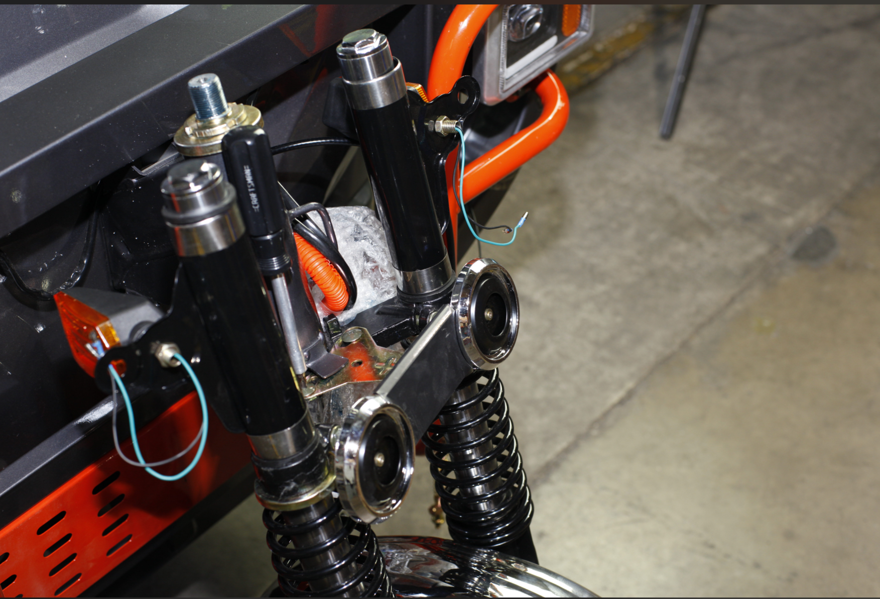
3.5 Confirm Installation Position
Confirm that the connector has been correctly installed in position.
3.6 Insert Gasket
Place the gasket in the designated position to ensure proper sealing.

3.7 Install Outer Aluminum Shell
Place the outer aluminum shell into the corresponding position.

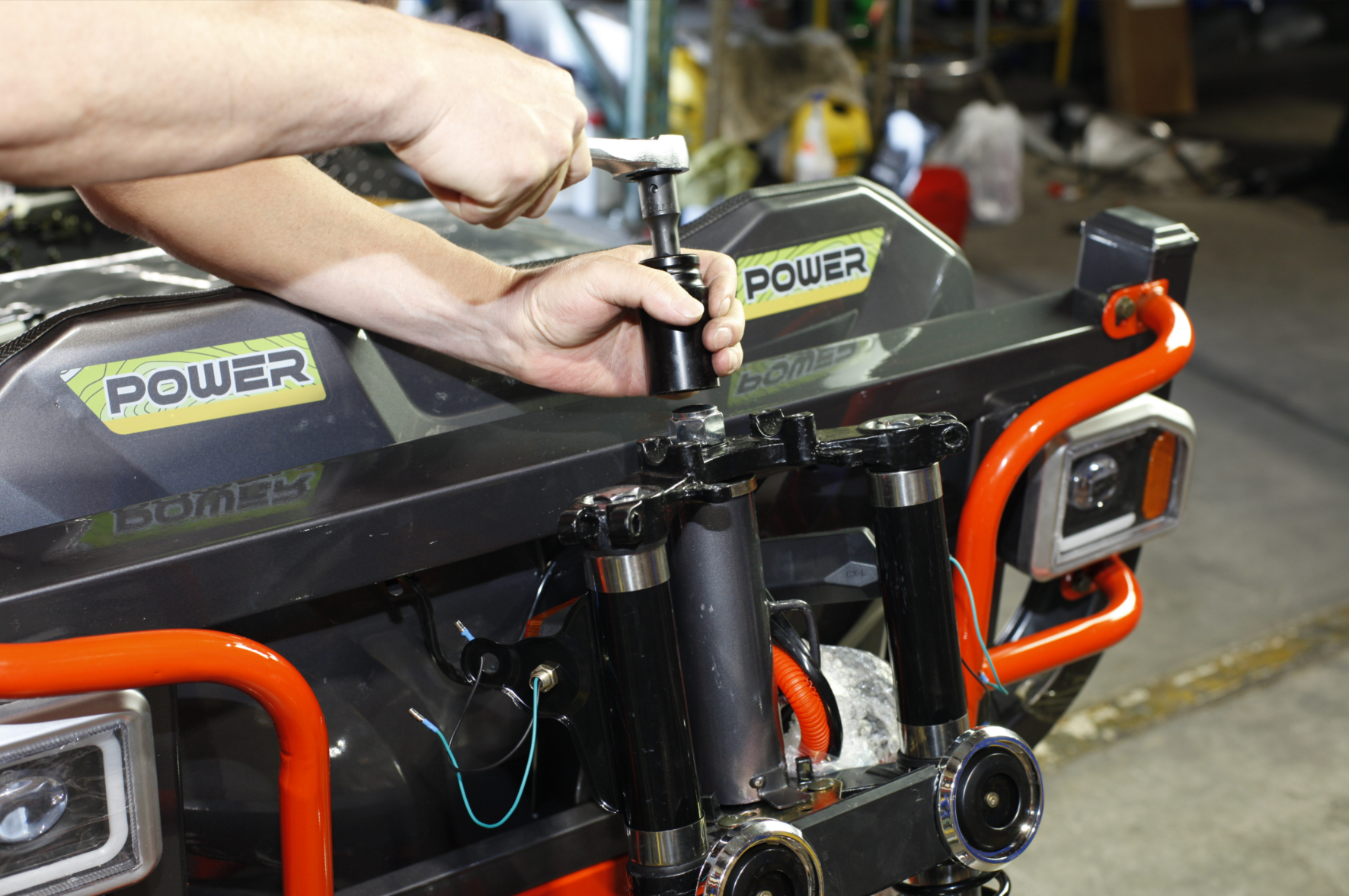
3.8 Tighten Aluminum Shell Screws
Insert aluminum shell screws and tighten using specialized tools.
3.9 Install Horn
Tighten the horn using a screwdriver.
3.10 Tighten Reinforcement Screws
Finally, tighten the reinforcement screws to provide double insurance.
4Electronic Component Installation
Install electronic devices and instrument components:
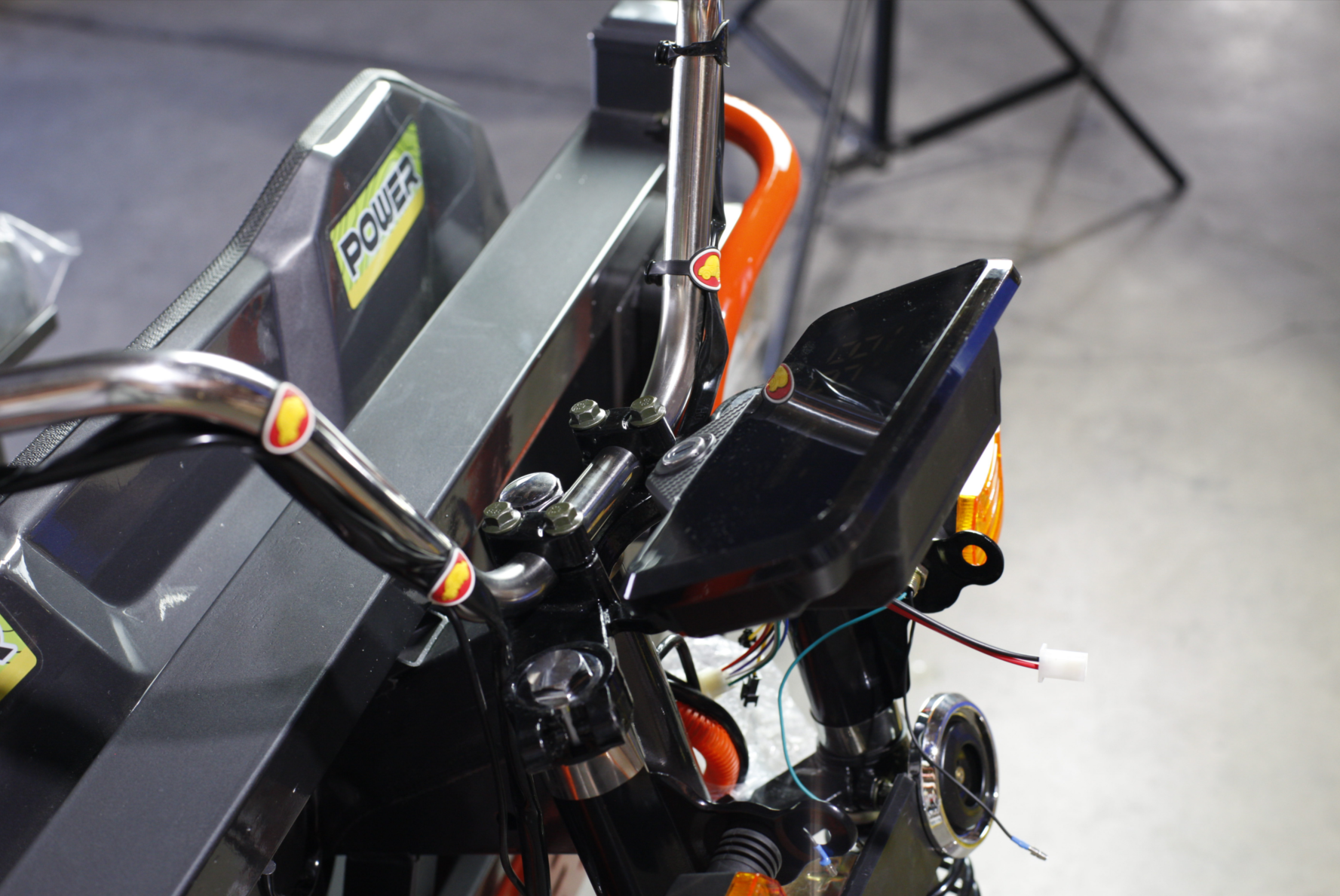
4.1 Install Instrument Panel
Tighten the instrument panel using hexagonal screws.

4.2 Install Handlebars
Place the handlebars into the designated groove.

4.3 Adjust Handlebar Position
Adjust the handlebar position to the proper angle and tighten securely.
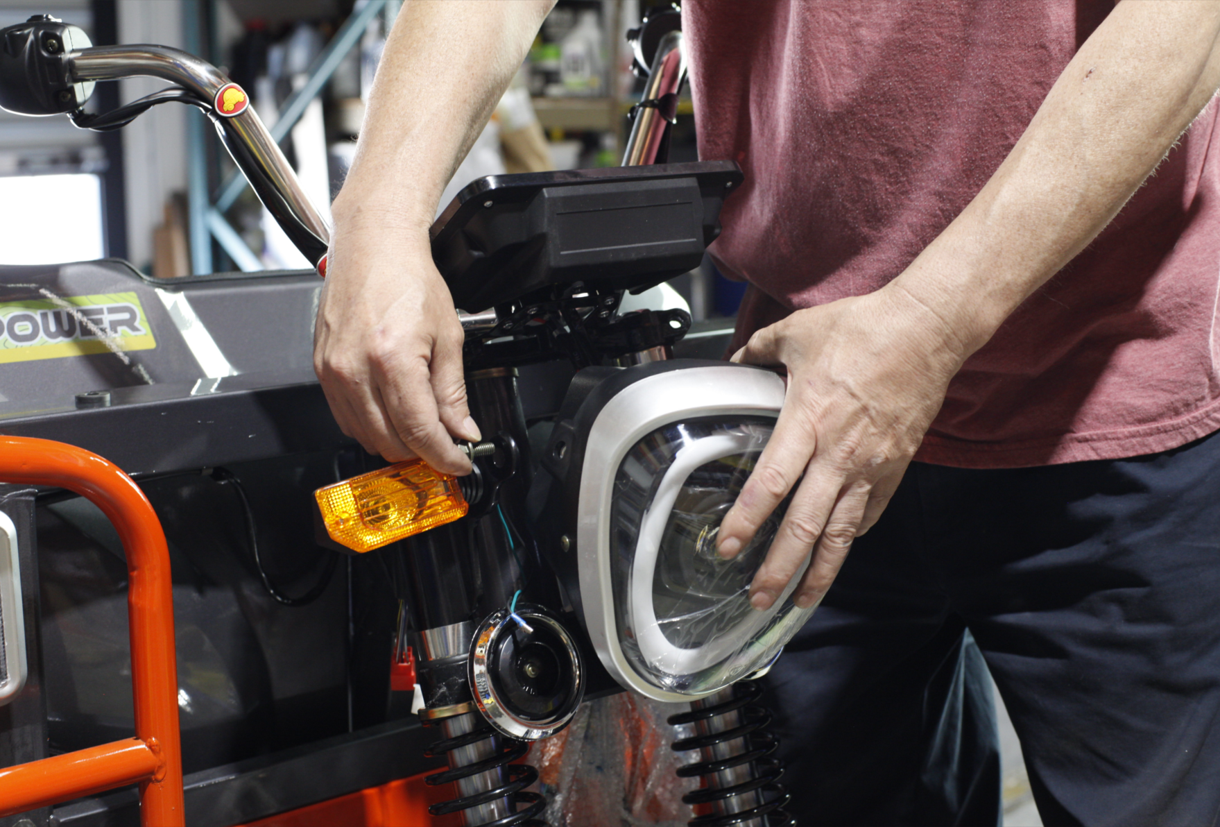
5Install Headlight
Install the headlight. The light has embedded screw nuts inside. Remove the threaded rod and pass it through the light bracket to tighten.
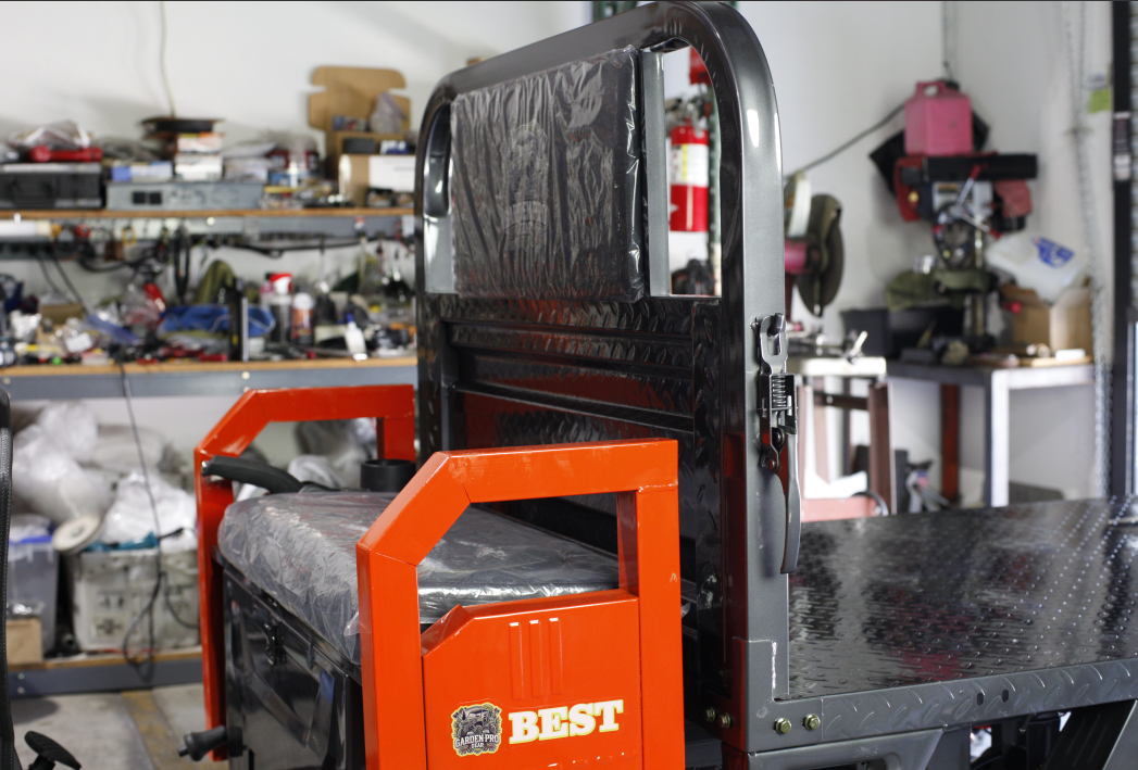
6Install Seat Cushion and Cargo Box
Install the connecting components between the seat cushion and cargo box.
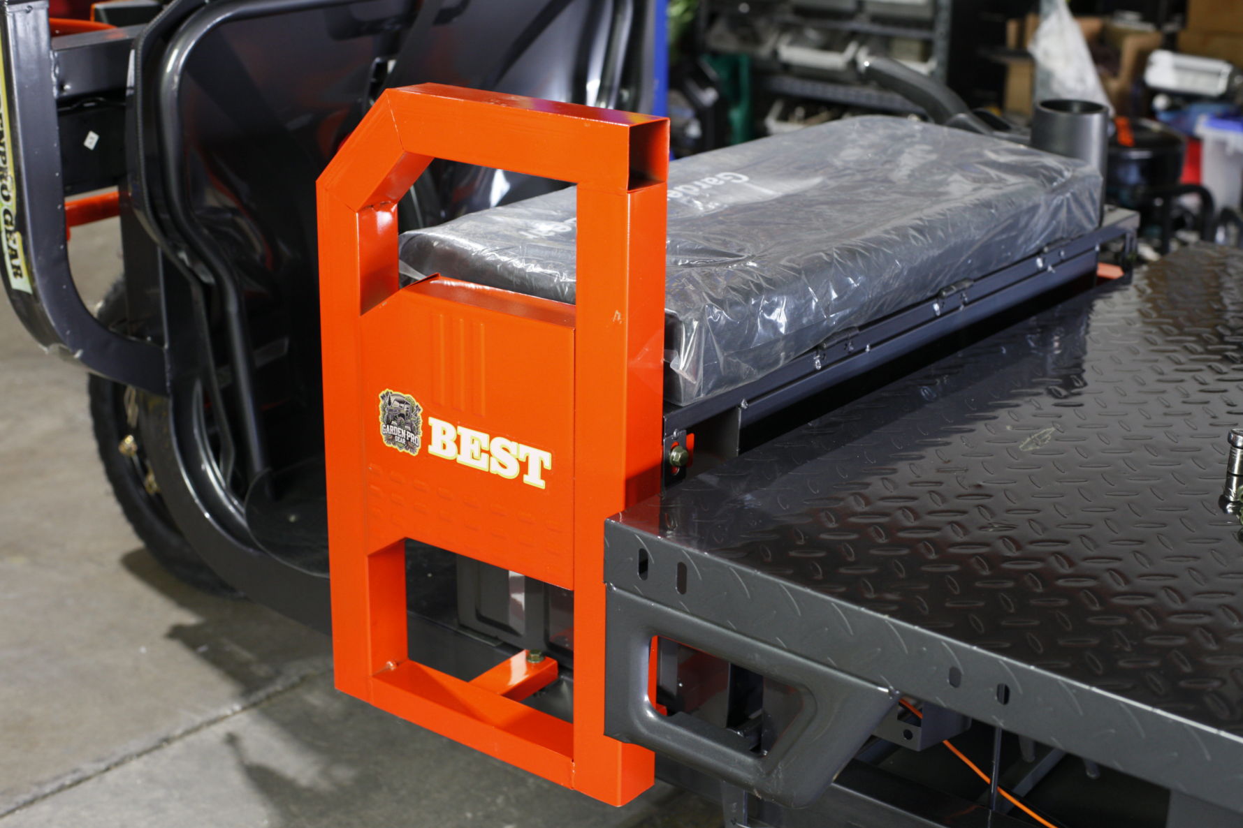
7Install Front Barrier
Install the front barrier and tighten the mounting screws securely.
8Side Door Installation
Install the side door by inserting screws and tightening them securely.
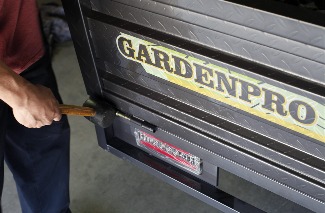
9Rear Door Installation
Install the rear door pins using a rubber hammer for gentle tapping.
10Complete Frame Inspection
After completing the overall frame assembly, perform the following inspections:
10.1 Check Tail Light Connections
Inspect the bottom tail light wiring connections to ensure they are properly connected.
10.2 Check Door Latch Connections
Verify that the front and rear door latch connections are functioning properly.
11Install Rearview Mirrors
Install and adjust the rearview mirrors to complete the overall vehicle assembly.
Installation Complete
🎉 Congratulations! You have successfully completed the electric utility vehicle installation. Please double-check all connections and fasteners before use to ensure safety.